RadioPI - debugging
When it comes to DIY projects one rule that ALLWAYS applies is that it takes longer than originally planned :-/
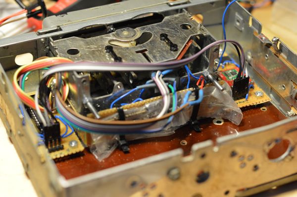
I´m currently debugging the radio module for my raspberry pi based retro-car-radio project and I realized that debugging software is far easier that debugging a hardware module. I already found out that it´s a stupid idea to shorten some of the coppertraces by making the circuit board touch the metal housing of the radio and I forgot to solder in a resistor.
I also found out that it´s a bad idea to accidentally remove some of the smd parts of a raspberry pi (RIP) and that the sd card holder of a pi is not very stable :-/
currently I´m trying to find a replacement part for a broken variable resistor - but theeeeeen .... nearly there, really, this time for sure, what could possible go wrong?
Stay tuned :-)
RadioPI hardware part 1
Yesterday I started mounting the components for my raspberry pi based retro car radio into the housing of the blaupunkt radio from the 60ties.
And I learned a lot - the hard way :-)
- For example that USB cables need an astonishing amount of space - even when folded and tied down with cable binders.
- USB-connectors are really, really, REALLY large - even if they are called micro usb.
- Drilling holes into ferromagnetical materials is a bad idea when you have two small speakers and a magnetic screwdriver laying on your desk - even it looks very funny
So there will be a unplanned part2 of the hardware session after I found shorter USB cables preferably with smaller connectors :-/
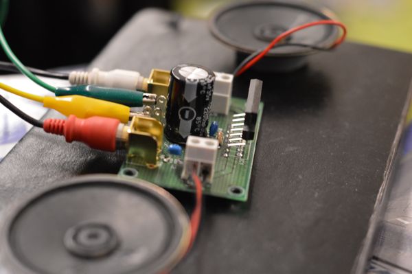
RadioPI - finalizing the audio module
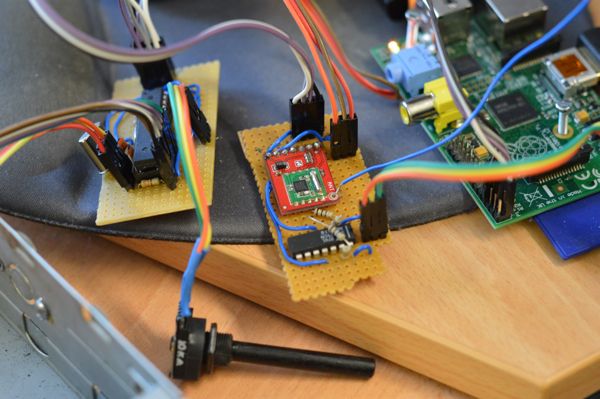
Today I soldered the radio module for my rapsberry pi based car radio. This was the last soldering/electronic challenge for this project now I only need to finish the software (= easy) and the hardware problems (= somewhat outside of my comfort zone :-))
The audio board consists of a AR1010 breakout board from sparkfun that connects via i2c and a simple preamplifier for the radio signal. The 3 connector on the right side go to the analog audio out of the raspberry pi.
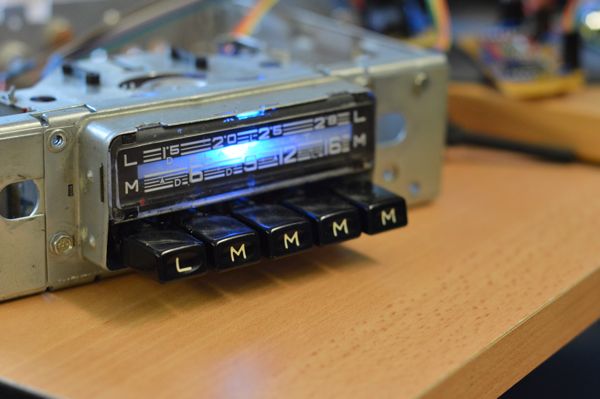
Day 30 of 30DaysOfCreativity - RadioPI interface module
Today I finished the interface module for my raspberry pi based retro car radio. The module interfaces the buttons, the variable resistor and a RGB-led using an ATMega 328p running an arduino firmware.
This is my day 30 project for 30daysOfCreativity but I think I will need to extend my 30 days a bit so I can finish this project :-)
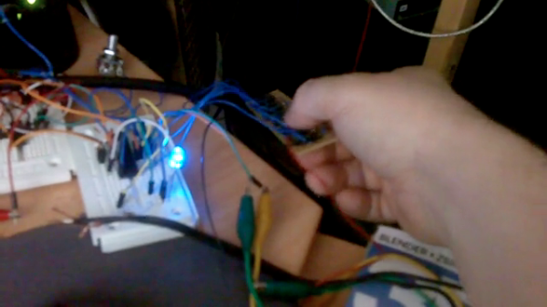
Day 28 of 30daysofcreativity - testing the radiopi software
today I started to write and test the software for my raspberry pi and arduino based retro car radio. Here is a short video that shows how the switching of the stations works. There are 4 slots for the stations the 5th slot turns on the airplay mode
Day 27 of 30daysofcreativity - testing the amp module
Today I tested the amplifier module for the raspberry pi based radio. Now I need to write the software for controlling the radio using the buttons and create circuit boards for the modules that live currently on breadboards
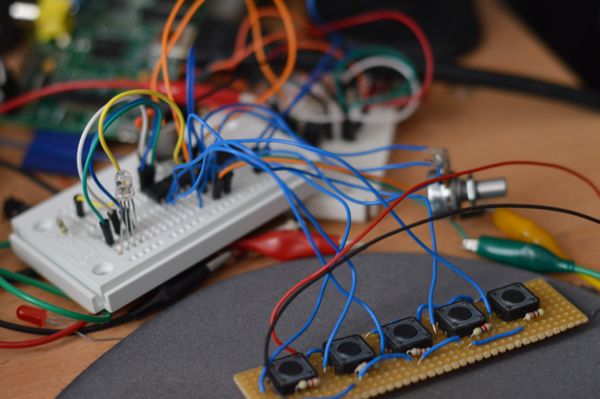
Day 26 of 30DaysOfCreativity - prototyping the controls
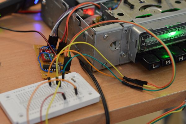
Today I hooked up the RGB led, the buttons and the potentionmeter to my breadboard arduino. I run the ATMega328P with a 20Mhz crystal and 3.3V which works pretty well. All my problems with I2C stability have disappeared now. The potentiometer is hooked to A0, the buttons are on D9 to D14 and the RGB led is connected to D6, D7 and D8. If the I2C master sends 1,2 or 3 the led color is changed, otherwise the slave sends the value of the potentiometer and the state of the buttons.
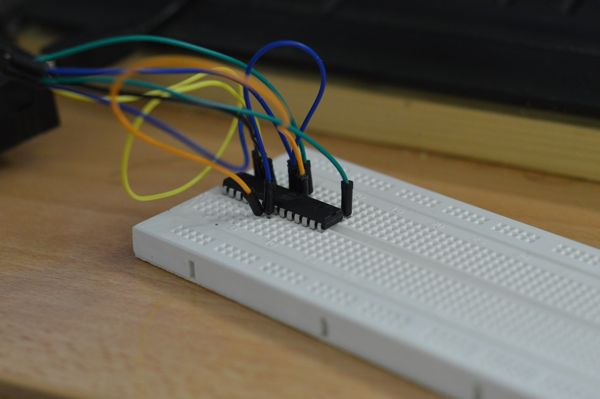
Day 24 of 30DaysOfCreativity - a breadboard arduino
Originally I planned to interface the hardware of the blaupunkt car radio from the 60ties using an attiny85 and an attiny2313 talking to the raspberry pi via i2c. But unfortunately this setup seems to be very unstable at the moment and I can´t get the i2c slaves to work properly. So I build a breadboard arduino today. I will try to hook the buttons, RGB-leds and the variable resistor and add a new i2c interface tomorrow.
So I have a Raspberry PI, an Arduino, some 3D printed parts, custom electronics, an interface to Apple iDevices, a retro car radio housing, .... hmmmmmmmm - Have I forgotten something?
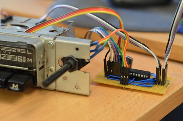
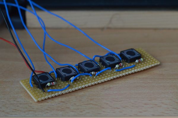
Day 23 of 30DaysOfCreativity - Buttons for the raspbery car radio
Today I soldered a board to interface the push buttons of the blaupunkt car radio that gets a new raspberry pi based brain. I tested the buttons with an arduino which worked very well. Then I tried to replace the arduino with an attiny2313 running the arduino-core firmware and the TinyWireS library, but unfortunately the setup is very instable - will have to debug this tomorrow
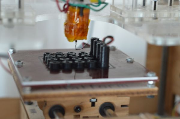
Day 21 of 30daysOfCreativity - 3D printed spacers
I'm currently placing a raspberry pi and an AR1010 based radio chip into the housing of a blaupunkt car radio from the 60ties for my friends VW typ 3 wilson. To mount the electronic parts I printed a bunch of spacers which I created using openscad.
you can download the openscad file here or the stl file here