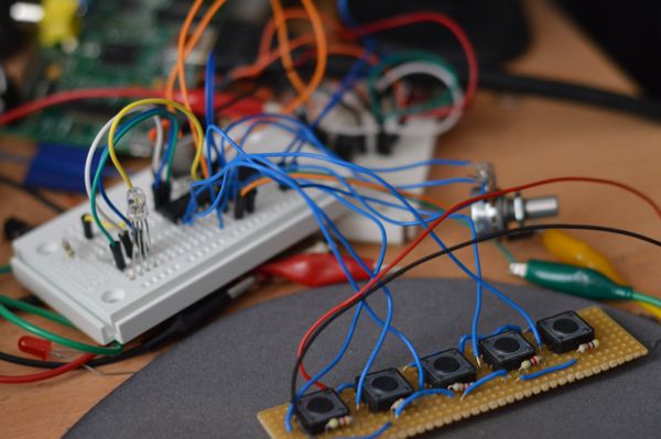
Day 26 of 30DaysOfCreativity - prototyping the controls
Today I hooked up the RGB led, the buttons and the potentionmeter to my breadboard arduino. I run the ATMega328P with a 20Mhz crystal and 3.3V which works pretty well. All my problems with I2C stability have disappeared now. The potentiometer is hooked to A0, the buttons are on D9 to D14 and the RGB led is connected to D6, D7 and D8. If the I2C master sends 1,2 or 3 the led color is changed, otherwise the slave sends the value of the potentiometer and the state of the buttons.
This is the code that creates the i2C slave on the arduino side
#include <Wire.h>

#define ADR 0x22

int analog;
int buttons;
byte state;
byte data[3];

void setup() {
  data[0] = 0;
  data[1] = 0;
  data[2] = 0;

  for ( int i=0; i<5; i++) {
    pinMode( i+9, INPUT );
  }

  pinMode( 6, OUTPUT );
  pinMode( 7, OUTPUT );
  pinMode( 8, OUTPUT );

  buttons = 0;
  analog = 0;

  digitalWrite( 6, HIGH );
  digitalWrite( 7, HIGH );
  digitalWrite( 8, LOW );

  Wire.begin( ADR );
  Wire.onReceive( receiveEvent );
  Wire.onRequest( requestEvent );
}

void receiveEvent( int c ) {
  while ( Wire.available()) {
    state = Wire.read();
    if ( state == 1 ) {
      digitalWrite( 6, LOW );
      digitalWrite( 7, HIGH );
      digitalWrite( 8, HIGH );
    } else if ( state == 2 ) {
      digitalWrite( 6, HIGH);
      digitalWrite( 7, LOW );
      digitalWrite( 8, HIGH );
    } else if ( state == 3) {
      digitalWrite( 6, HIGH);
      digitalWrite( 7, HIGH );
      digitalWrite( 8, LOW );
    }
  }
}

void requestEvent() {
  data[0] = (byte) (analog >> 8);
  data[1] = (byte) (analog & 0xFF);
  data[2] = (byte) (buttons & 0xFF);

  Wire.write( data, 3 );
  buttons = 0;
}

void loop() {
  int a = analogRead(0);
  delay(5);
  int b = analogRead(0);
  delay(5);
  int c = analogRead(0);

  analog = (a + b + c)/3;

  for( int i=0; i<5; i++ ) {
    if (digitalRead( i+9 ) == HIGH ) buttons |= ( 1 << i );
  }
}
and is a short python test program that runs on the raspberry. The code cycles through the rgb led and then reads the state of the buttons and the potentiometer
import smbus
import time
bus = smbus.SMBus(1)

adr = 0x22

bus.write_byte( adr, 3 );
time.sleep(1)

bus.write_byte( adr, 2 );
time.sleep(1)

bus.write_byte( adr, 1 );
time.sleep(1)

res = bus.read_i2c_block_data( adr, 0xFF, 3 );

a = res[0]
b = res[1]
c = res[2]

print (a * 255 + b), bin(c)


See also:
Day 30 of 30DaysOfCreativity - RadioPI interface module
Day 28 of 30daysofcreativity - testing the radiopi software
Day 24 of 30DaysOfCreativity - a breadboard arduino
Day 19 of 30DaysOfCreativity - RGB led for the Raspberry PI based Radio
RadioPI - debugging
Day 28 of 30daysofcreativity - testing the radiopi software
Day 24 of 30DaysOfCreativity - a breadboard arduino
Day 19 of 30DaysOfCreativity - RGB led for the Raspberry PI based Radio
RadioPI - debugging